Table of Contents
Wireguard Plugin For OMV6
Summary
- The main purpose of Wireguard is to facilitate the connection of two devices over the Internet securely.
- Openmediavault-wireguard integrates into the OMV interface trough the Tunnels and Clients tabs the ability to generate one or more point-to-site encrypted VPN Wireguard connection networks with two clicks.
- Wireguard's point-to-site connection allows access to the entire network where the server is.
- This is the default configuration in the plugin.
- You will be able to access all your shared folders and all the services you have configured on your local network as if you were there.
- By default all client traffic will be forwarded through the VPN connection (it is configurable), providing privacy through the encrypted connection. You can be connected to a public Wi-Fi network and browse with the security that nobody sees what you do.
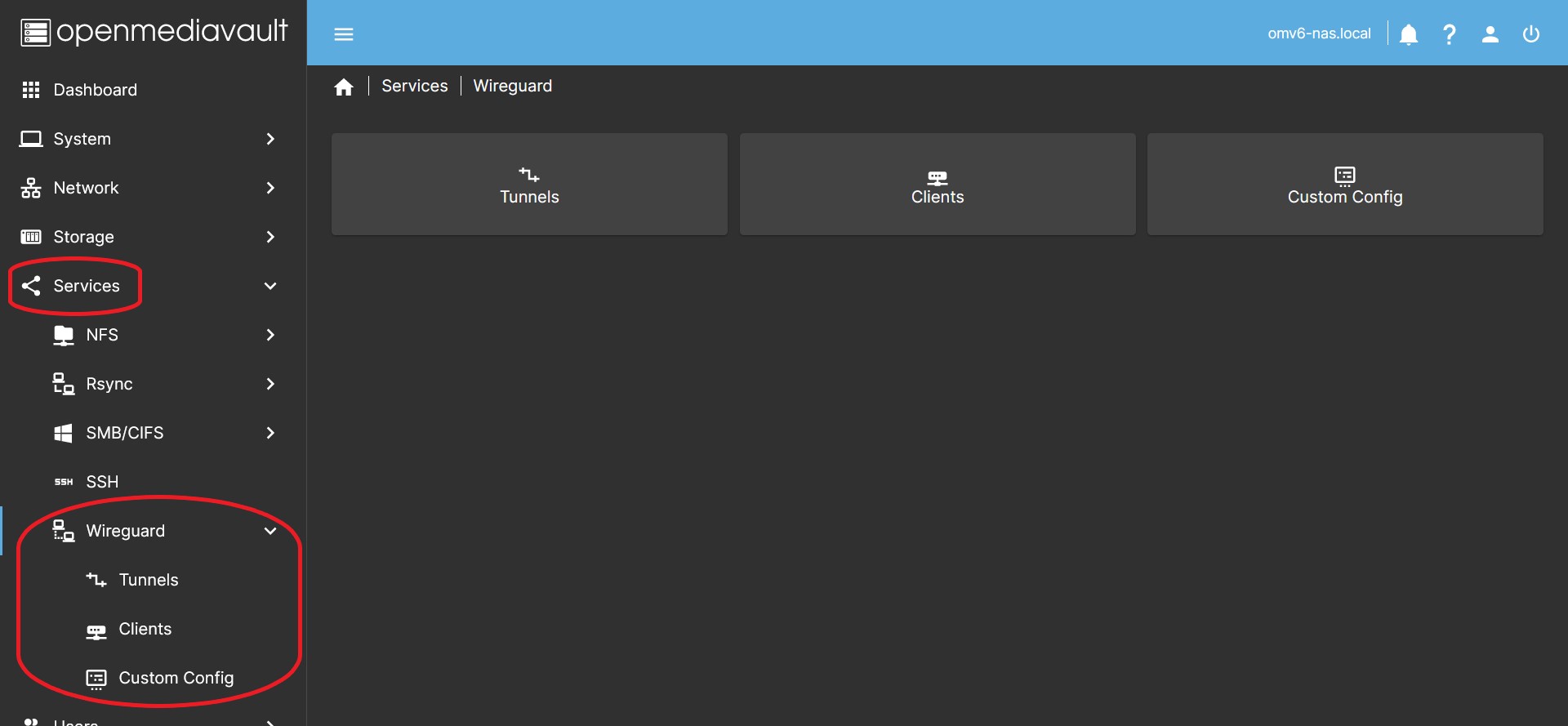
- The Custom Config tab allows you to make configurations according to specific needs. You can implement any Wireguard network topology.
- The point-to-point connection allows the connection between two servers, communicating only with each other. For example to make remote backups.
- The site-to-site provides a connection between two networks so that any IP on a local network is able to communicate with any IP on another local network.
- You can implement any other typology you need, Hub and Spoke…
- The fundamental principle to understand any wireguard connection configuration is that the connection is made peer to peer. It's not really a typical client-server configuration. When we talk about a Wireguard server, we are actually talking about a single peer (server) that makes simultaneous connections on the same network with different peers (clients). Despite this and to make it easier to understand, in this document you will find references to servers and clients.
Third Party Software Note
 While this OMV plugin makes the wireguard package easy to integrate into openmediavault, the wireguard package itself was created by a third party. See the project / author's → Wireguard web page for more detailed information and support.
WireGuard® is an extremely simple yet fast and modern VPN that utilizes state-of-the-art cryptography. It aims to be faster, simpler, leaner, and more useful than IPsec, while avoiding the massive headache. It intends to be considerably more performant than OpenVPN. WireGuard is designed as a general purpose VPN for running on embedded interfaces and super computers alike, fit for many different circumstances. Initially released for the Linux kernel, it is now cross-platform (Windows, macOS, BSD, iOS, Android) and widely deployable. It is currently under heavy development, but already it might be regarded as the most secure, easiest to use, and simplest VPN solution in the industry.
Prerequisites
- OMV-Extras must be pre-installed.
Installation
In OMV6's GUI:
Under System > Plugins, find and highlight openmediavault-wireguard 6.X, and click the install button.
Management of a Tunnel
Configuring a tunnel
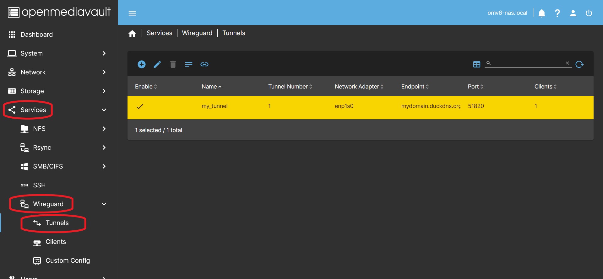
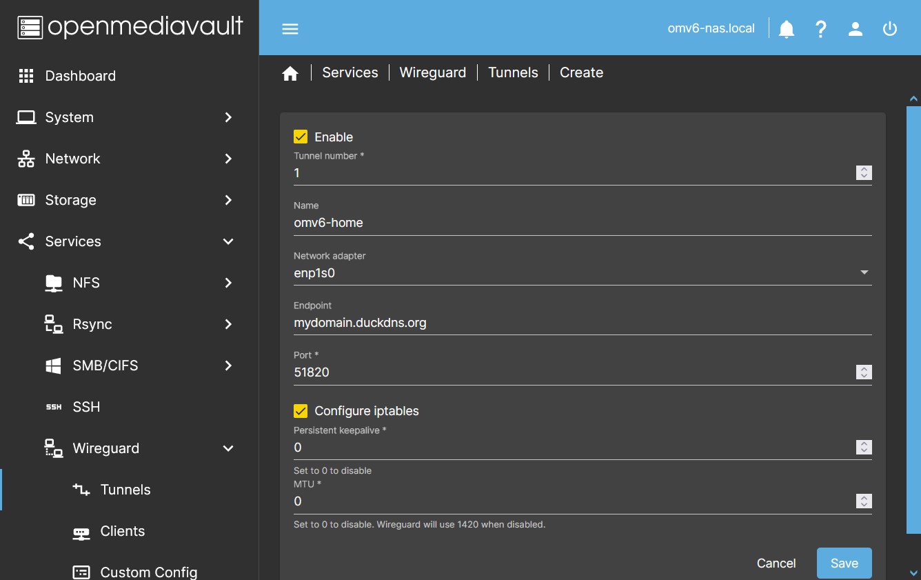
- In the OMV GUI go to Services > Wireguard > Tunnels Press the Create button.
- In the dialog box enable the tunnel and fill in the fields:
- Name You can name the tunnel to identify it later.
- Network Adapter Click on the Network adapter dropdown menu and choose your adapter.
- If you are not sure which adapter you have, you can go to Network > Interfaces to find out.
- Endpoint You must type the public IP address of your router or the name of a domain that points to the public IP of your router. This endpoint will direct the client to the public IP of your router to initiate the connection.
- If your IP is dynamic (can change unexpectedly) and you don't have a domain, you can get a free domain on the internet and set up an automatic update of your public IP for that domain. At the end of this document there is a procedure to do it using duckdns.
- Check your public IP. This website can be useful, whatismyip.com If it is not the same one that is established in your router, it is because you are behind CGNAT. Only your ISP can fix it.
- Check that the domain points to your IP. This website can be useful, www.whatsmydns.net Check that your domain points to your public IP.
- Port field, type the port you want to use for the connection, usually it is 51820.
- You can choose any available port, it must not be occupied on your system by any service or by another wireguard tunnel.
- Remember that you must open this port in the router and direct it to the IP of your server and with the same port. Use the UDP protocol. If you don't know how to do it, consult the manual of your router.
- Configure iptables By default this will generate the settings in iptables to allow traffic on your internal network from outside.
- If for some reason you need the plugin not to configure iptables, you can do so by clearing this checkbox.
- The default setting is:
PostUp = iptables -A FORWARD -i %i -j ACCEPT; iptables -A FORWARD -o %i -j ACCEPT; iptables -t nat -A POSTROUTING -o [NETWORK INTERFACE] -j MASQUERADEPostDown = iptables -D FORWARD -i %i -j ACCEPT; iptables -D FORWARD -o %i -j ACCEPT; iptables -t nat -D POSTROUTING -o [NETWORK INTERFACE] -j MASQUERADE- …
Note The plugin enables IP forwarding on the host by default. So it is not necessary to add any sysctl -w net.ipv4.ip_forward=1type instruction in the interface.- …
- Persistent keepalive By default it is disabled. Set a value, such as 25, so that a hello is sent through the tunnel every 25 seconds.
- Activate only if necessary for some reason. One of wireguard's security principles is to be silent on connections.
- MTU By default it is disabled. Generally this equates to
MTU=1420. Set a value if you need to modify this parameter. wg-quick does not support values below 1280. If you don't know your network parameters, the value 1380 should work fine in most cases. The upper limit is 9999.- If no value is set, wireguard will set it from the existing network configuration. Typically this value is 1500, so wireguard will automatically set
MTU=1420, since the length of the header used by wireguard is subtracted (the longest is 80 bytes for IPv6). - You may need to set a smaller value if your connection works through PPPoE or VLAN, in this case you must subtract the header length added by this network. If you don't, packets will be fragmented, more headers will be added to those packets, and the result will be a slower connection.
- Your ISP can also limit this value, check with him what is his restriction.
- Higher values can be set for higher speed networks.
- Click the Save button and accept the changes. At this time the connection is configured and active.
| Note | |
|
It is completely necessary and mandatory that our operator provide us with a public IP address, if we have CG-NAT in our connection we will not be able to access from outside. This is something completely normal, and it is the first thing you should make sure of for it. Of course, if we are opening a port on the router, we have to make 100% sure that our server's firewall is not interfering with the communication. | |
Editing a tunnel
- If you need to edit a tunnel for any reason you can select the tunnel and press the Edit button.
- You can do it at any time, but if you have already configured the clients, the configuration of the clients will also be modified.
Delete a tunnel
- Press the Delete button to delete a tunnel, select it previously.
See the Tunnel Config
- Press the Tunnel Config button to see the tunnel configuration, select it previously.
- Useful in case of using the tunnel as a template for a custom config.
Management of a Client
Configuring a Client
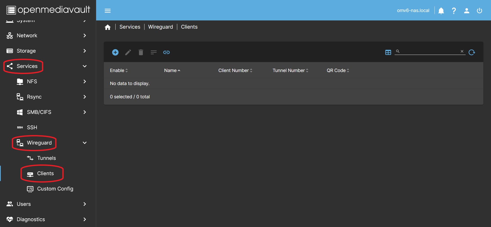
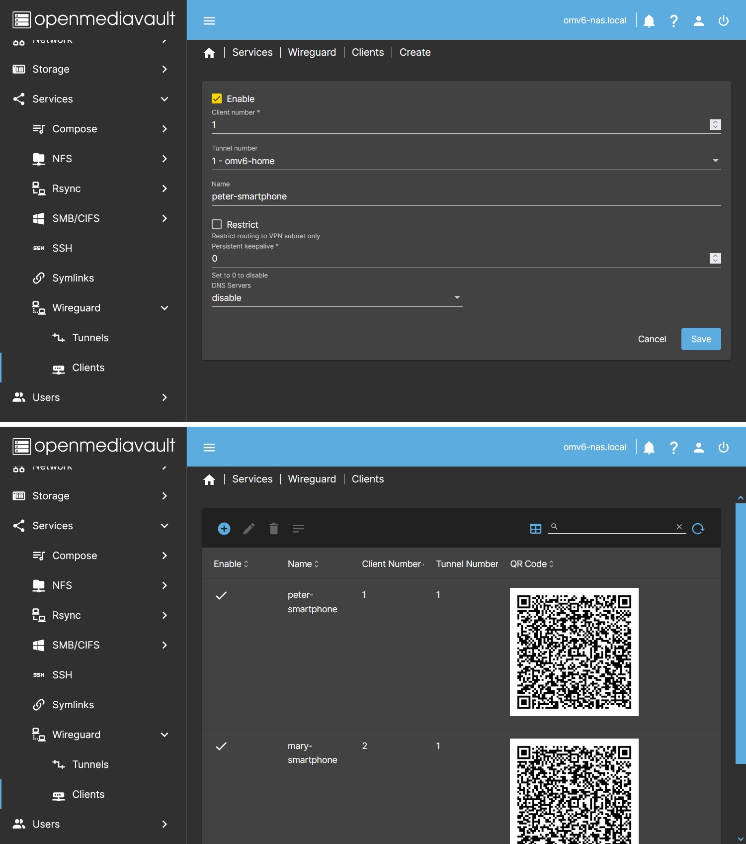
- In the OMV GUI go to Services > Wireguard > Clients Press the Create button.
- In the dialog box enable the client and fill in the data:
- Client number It must not coincide with that of other clients.
- Tunnel number You must assign the client to one of the previously created tunnels.
- Name You can name the client to identify it later.
- Restrict button. The default setting is to leave it unchecked, this will set AllowedIPs to 0.0.0.0/0 and all traffic will be routed through the tunnel. If you press it, only traffic directed to the wireguard network will be routed. To access the server services you must write the IP of the server, if the tunnel is number 1 the IP will be 10.192.1.254, if the tunnel is number 2 the IP will be 10.192.2.254… After that add
:and the service port. For example, to access Jellyfin it would be10.192.1.254:8096if it is tunnel number 1. You will not be able to access other services on your local network outside of your server. If you need that you must edit the client configuration and set the local network range in the AllowedIPs field. For exampleAllowedIPs = 192.168.1.0/24(adapt it to your case) - Persistent Keepalive The default setting is to leave it blank. In some cases it may be necessary to set a value here to keep the connection active. A suitable value is usually 25 (Every 25 seconds the client will send a packet to the server).
- DNS Servers The default setting is to leave it blank. In some cases it may be necessary to establish a DNS server for the client to communicate correctly on the local network. The usual thing will be to establish the IP of the router. The menu will show the existing value in resolv.conf in case you want to copy it to the field on the right.
- Click Save. At this point, if you have already activated the tunnel and the client, the connection will be up and running.
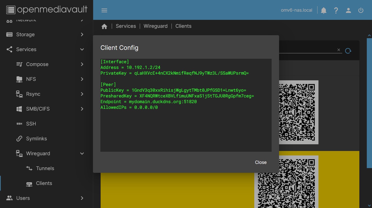
- By pressing the button Client Config you can see the client configuration file, you can copy and paste the text in a file to configure the connection in the client. If you do it this way, add the ending “.conf” to the created file. Treat this file like a password, it is the access key to your network. Once the connection is configured, it is advisable to delete this file for security.
- A QR will appear in the table (if the client is enabled), which you can scan from a smartphone to configure the connection without having to copy a file. If you need to send it you can take a photo. Treat this image as a password, it is the access key to your network.
- Use a different client configuration for each client. If you configure the same connection on several clients at the same time, they will not be able to connect simultaneously.
Editing a Client
- By pressing the Edit button you can modify the parameters or disable the client. Select it previously.
Delete a Client
- Pressing the Delete button will remove the client from the tunnel. Select it previously.
- To remove a client in an active tunnel you must first deactivate the client.
See the Client Config
- Press the Client Config button to see the client configuration, select it previously.
- Useful in case of using the client as a template for a custom config.
- Useful in case of configuring a client using a file instead of the QR image.
Management of a Custom Config
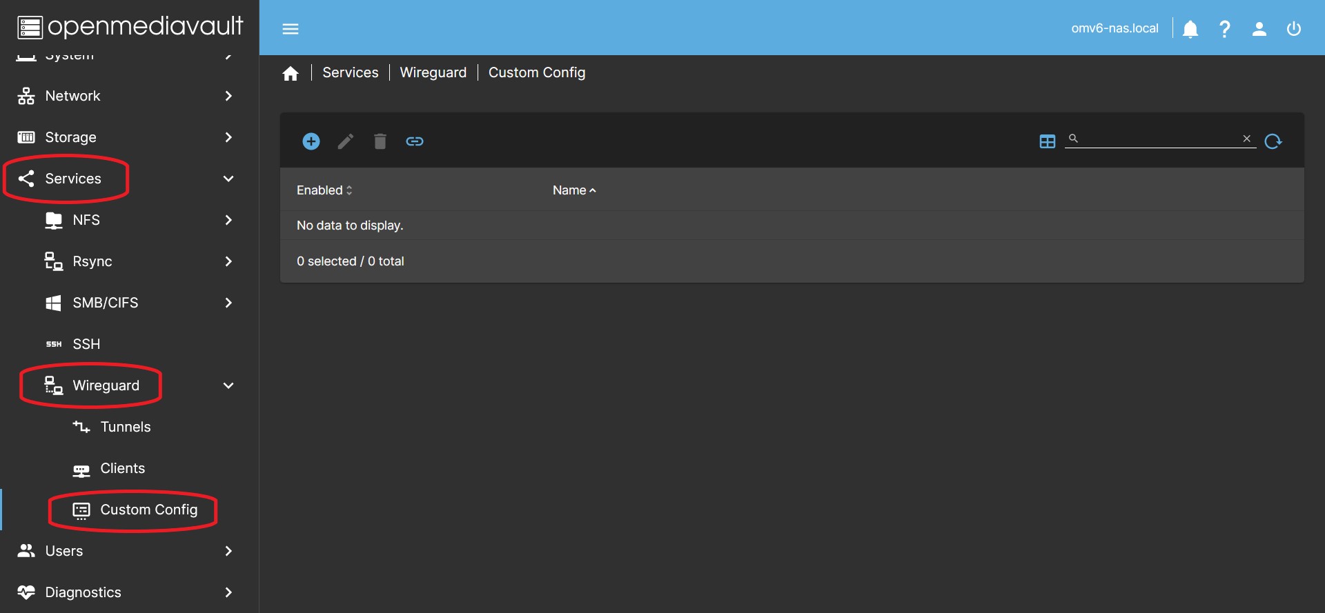
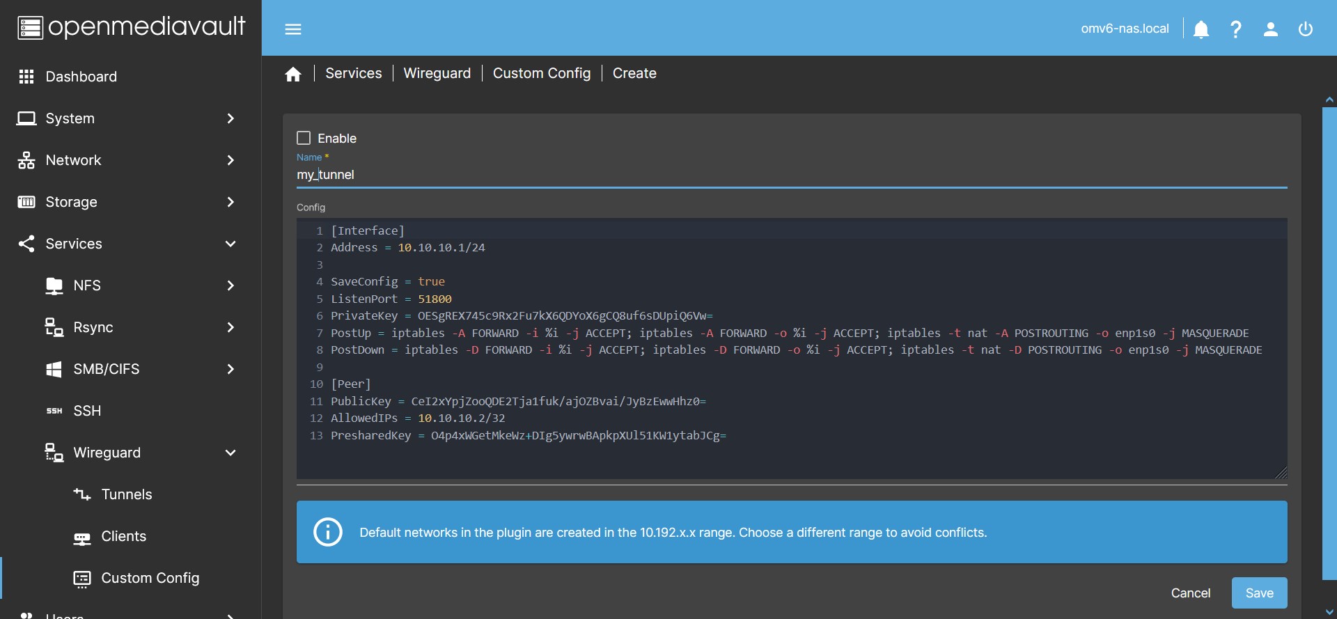
This tab allows you to create a tunnel with the custom settings you need. It allows to open an editing window where you can paste the configuration from a text file, therefore, you can choose the parameters you need for the tunnel.
If you need to configure a tunnel to connect the point-to-point server with another server, or any other network topology, you must do so in this tab, since it allows you to manually define keys, networks and other necessary parameters.
Create a Custom Config
- In the OMV GUI go to Services > Wireguard > Custom Config and press the Create button.
- In the Name field type the name of your custom tunnel.
- The name of the service will be
wgnet_NAMEwhereNAMEis the name chosen for the tunnel. - Due to an existing restriction of name lengths the chosen name cannot have more than 9 characters, the GUI does not allow entering longer names.
- In the Config field write the configuration content of your tunnel following the Wireguard rules.
- You can see how to do it on the Wireguard website. Or use a template following the suggestion at the bottom of this section.
- If you need special topologies you can find them on the procustodibus.com website.
- Note that the networks created by the plugin in the Tunnel and Client tabs are generated in the
10.192.x.xnetwork range. Therefore, choosing networks in this range may cause conflicts. In that case the service will not start and the plugin will throw an error.
- Click Enable to activate the tunnel.
- Press the Save button and accept the changes.
- The configuration will be stored in the OMV database.
- If you pressed the Enable button, the service will be generated and the tunnel generated will be put into operation.
- If you did not press Enable, the configuration will be saved but the tunnel will remain inactive.
- If the tunnel is active, you can see in the
/etc/wireguardfolder the generated configuration file that the service is using.- Do not make any changes to this file, the plugin will overwrite it. If you need to edit the configuration do it in the plugin GUI.
| Tip: Use templates to automatically generate keys. | |
|
If you are creating a custom tunnel from scratch and want to avoid creating the keys manually, you can create a tunnel and a client (or several) and use them as templates: Create a tunnel in the Tunnels tab and activate it and create a client in the Clients tab and activate it. In the Tunnels tab, select the tunnel you have created and click the Tunnel Config button. Copy the text to the clipboard and go to the Custom Config tab. Create a new tunnel and paste the text in the dialog box. Save the changes without activating the tunnel. Go to the Clients tab and select the client you have created. Click the Client Config button and copy the text to a text file. This will be the starting point with the keys for your peer. Delete the generated client and tunnel that you used as templates. You are now ready to edit your custom tunnel and activate it. Modifies the range of networks to move away from the networks generated by the plugin. Modify the rest of the parameters according to your needs. | |
| Note | |
| In the procedures section of this document there is a procedure to create a point-to-point tunnel. | |
| Note | |
The plugin enables IP forwarding on the host by default. So it is not necessary to add any sysctl -w net.ipv4.ip_forward=1 type instruction in the interface.
| |
Edit a Custom Config
- In the OMV GUI go to Services > Wireguard > Custom Config and select the tunnel you want to edit (yellow color)
- Press the Edit button.
- In the window modify the parameters you need.
- Press the Save button and accept the changes.
Delete a custom tunnel
- In the OMV GUI go to Services > Wireguard > Custom Config and select the tunnel you want to delete (yellow color)
- If it is active you must disable it previously.
- Press the Edit button.
- Press the Enable button to disable it.
- Press the Save button and accept the changes.
- Select the tunnel again, now inactive.
- Press the Delete button.
- Click Yes and accept the changes.
How to configure a smartphone or pc
If the client is a smartphone (android or iOS)
- Install the Wireguard App on your smartphone.
- Open the app and tap the + button to add a connection. Tap the option to scan a QR code. Alternatively it can be configured from a text file in the same way as a PC (see next point).
- In the OMV interface go to Services > Wireguard > Clients Scan the corresponding customer's QR code from the smartphone.
- Type a name for your connection on your smartphone and tap OK.
- Your client is configured. You just have to activate the connection and you will have access to the network of your server.
| Note | |
|
Depending on your router settings, the connection may not work if you are connected by Wi-Fi on the same network as the server. You can disable the Wi-Fi connection of the smartphone in this case and connect with data on the smartphone. This way you can test your connection. | |
If the client is a PC (Linux, MacOS or Windows)
- Install the Wireguard application on the PC. On the official wireguard page there are instructions for all platforms.
- In the OMV interface, go to Services > Wireguard > Clients click the Client Config button. A window with client settings will open. Copy and paste the text into a file and add the extension “.conf” to it, save it on the desktop of the PC you want to configure.
- On the PC where you are going to configure the wireguard connection, open the Wireguard app and click add connection from file. Select the file from your desktop and click ok.
- If there is no add connection from file option, you can create a new connection and paste the contents of the file inside.
- Your client is configured. You just have to activate the connection and you will have access to the network of your server.
| Note | |
|
Depending on your router settings, the connection may not work if the PC is connected to the same network as the server. If the PC has Wi-Fi, you can share a data connection via Wi-Fi from the smartphone and connect to it from the PC. This way you can test your connection. | |
How to split the tunnel traffic
Useful if you connect to a remote network but at the same time want to access your local network. This can be achieved if the network ranges are different on these two networks.
- If you need to split the tunnel traffic for some reason you can edit the AllowedIPs field on the client.
- The AllowedIPs field filters the addresses that will navigate through the Wireguard network. Addresses outside of the defined range will not be routed through the Wireguard tunnel.
- You can modify this field on the client, this will only affect the client, the configuration on the server will not change, the server will only receive more or less traffic.
0.0.0.0/0means all IP addresses, that is, all traffic.
- Changing the value
0.0.0.0/0to something else will restrict tunnel traffic to the specified IP range. For example, if you only want to forward traffic to access your 192.168.1.x network you can specify192.168.1.0/24(This includes all IPs between 192.168.1.1 and 192.168.1.254)- With this configuration, the client will divert the traffic addressed to any IP address between 192.168.1.1 and 192.168.1.254 through the Wireguard tunnel, the rest of the traffic will follow its normal course through another available network interface.
How to Point-to-point tunnel configuration
Point to point. Standard tunnel.
Wireguard's point-to-point configuration creates a remote connection between two peers so that they can only communicate with each other, without sharing any other points on the local network of each peer.
It's a simple setup, each peer can only see the IP of the other peer. The rest of the IPs of the local network are restricted in this connection. Logically, each peer can access all the ports of the other peer, therefore it is able to access all its services on that IP.
One of the two peers is the one that opens the connection with the other peer and keeps it open so that the other peer can also link. We will see it later.
The point-to-point configuration is useful, for example, in situations where you need to create remote backup jobs from one server to another. For example, a peer can access an rsync module created by the other peer if given the credentials to do so.
The procedure is the next:
Configuration of the first server (peer 1)
- Use a tunnel and a client as templates to generate the keys. You can see how to do it at the end of the Create a custom config section.
- Edit the settings in the Custom Config tab as follows:
[Interface]
PrivateKey = Uses the previously generated TUNNEL PRIVATE KEY
ListenPort = 51500
Address = 10.15.15.1/32

[Peer]
PublicKey = Uses the previously generated CLIENT PUBLIC KEY
AllowedIPs = 10.15.15.2/32
- You can adapt the ListenPort field to your needs. Use a port that is free on your server.
- You can adapt the Address field to your needs. Make sure to use
/32for Netmask. This will ensure that the peer will only access the IP of the server. - Press the Enable button to activate the tunnel.
- Press the Save button and accept the changes.
Configuration of the second server (peer 2)
- On the second server, go to Services > Custom Config in the GUI and click Create
- Paste the content of the client file you generated on the first server into the window.
- Get rid of the parameters you don't need and keep the keys, so you end up with this configuration:
[Interface]
PrivateKey = Uses the previously generated CLIENT PRIVATE KEY
ListenPort = 51500
Address = 10.15.15.2/32

[Peer]
PublicKey = Use the previously generated TUNNEL PUBLIC KEY
AllowedIPs = 10.15.15.1/32
Endpoint = mydomain.com:51500
PersistentKeepalive = 25
- If you adjusted the values of the first peer, port and subnet, repeat it in this configuration.
- This peer will be the one that makes the connection and will keep it open.
- For this we need to indicate a domain to connect to. You can create one for free by following this procedure: How to set up a free domain with duckdns fix dynamic ip
- We also need to set the PersistentKeepalive value. This will send a minimum packet every 25 seconds (or whatever value you choose, 25 is enough) so that the peer 1 knows where to direct their communication if they want to make contact.
- Press the Enable button to activate the tunnel.
- Press the Save button and accept the changes.
You just need to make sure that the port set is open on both routers and that the domain point set on the peer 2 points to the public IP of the peer 1.
If you are sure of the above, the point-to-point tunnel is established. You can check this in the CLI from the first peer by running ping 10.15.15.2 and from the second peer by running ping 10.15.15.1 or whatever subnet you have set. The response should be something similar to this:
ping 10.15.15.1 (10.15.15.1) 56 (84) bytes of data.
64 bytes from 10.15.15.1: icmp_seq = 1 ttl = 64 time = 30.6 ms
64 bytes from 10.15.15.1: icmp_seq = 2 ttl = 64 time = 30.7 ms
64 bytes from 10.15.15.1: icmp_seq = 3 ttl = 64 time = 29.6 ms
64 bytes from 10.15.15.1: icmp_seq = 4 ttl = 64 time = 28.9 ms
^ C
--- 10.15.15.1 ping statistics ---
4 packets transmitted, 4 received, 0% packet loss, time 8ms
rtt min / avg / max / mdev = 28.877 / 29.934 / 30.677 / 0.775 ms
If it doesn't work check your domain and check that the ports are open on both routers.
Point to point. Variant with two Endpoints, silence in the connection.
Wireguard is characterized by being a silent connection. In the above case, only one of the two peers can initiate the connection since the other peer does not have an endpoint. Therefore, to allow the initiation of the connection from both peers, one of them must keep the connection open by sending a packet every so often (PersistentKeepalive).
We can achieve that the tunnel behaves silently when there is no communication and that both peers can initiate the connection, for this we must establish an Endpoint in each of the two peers. Of course to achieve this we must have a domain pointing to each server. We will call them in this case peer1.mydomain.com and peer2.mydomain.com
The previous configuration would look like this:
Peer 1.
[Interface]
PrivateKey = xxxxxxxxxxxxxxxxxxxxxxxxxxxxxxxxxxxxxxxxxx
ListenPort = 51500
Address = 10.15.15.1/32

[Peer]
PublicKey = xxxxxxxxxxxxxxxxxxxxxxxxxxxxxxxxxxxxxxxxxx
AllowedIPs = 10.15.15.2/32
Endpoint = peer2.mydomain.com:51500
Peer 2.
[Interface]
PrivateKey = xxxxxxxxxxxxxxxxxxxxxxxxxxxxxxxxxxxxxxxxxx
ListenPort = 51500
Address = 10.15.15.2/32

[Peer]
PublicKey = xxxxxxxxxxxxxxxxxxxxxxxxxxxxxxxxxxxxxxxxxx
AllowedIPs = 10.15.15.1/32
Endpoint = peer1.mydomain.com:51500
Point by point. Firewall configuration using iptables.
The above configuration allows the peers to talk to each other on any port. If you need it, you can restrict these communications to one or more ports using iptables as a firewall. This will cause each of the peers to reject any communication outside of what we need to establish.
Suppose we are setting up this tunnel to perform rsync synchronization from a module that supports connections on port 873 (you can customize it). In this case, it would be desirable for each server to only allow connections to that port, denying connections to any other service.
Suppose we have called the interface of each peer pp_peer1 in the plugin GUI. The plugin will end up calling that interface wgnet_pp_peer1. Similarly, in peer 2 the interface will be called wgnet_pp_peer2.
The configuration of the previous section would look like this after applying the iptables rules:
Peer 1.
[Interface]
PrivateKey = xxxxxxxxxxxxxxxxxxxxxxxxxxxxxxxxxxxxxxxxxx
ListenPort = 51500
Address = 10.15.15.1/32

# Firewall
PreUp = iptables -A INPUT -i wgnet_pp_peer1 -m state --state ESTABLISHED,RELATED -j ACCEPT
PreUp = iptables -A INPUT -i wgnet_pp_peer1 -m state --state NEW -p tcp --dport 873 -j ACCEPT
PreUp = iptables -A INPUT -i wgnet_pp_peer1 -j REJECT
PostDown = iptables -D INPUT -i wgnet_pp_peer1 -m state --state ESTABLISHED,RELATED -j ACCEPT
PostDown = iptables -D INPUT -i wgnet_pp_peer1 -m state --state NEW -p tcp --dport 873 -j ACCEPT
PostDown = iptables -D INPUT -i wgnet_pp_peer1 -j REJECT

[Peer]
PublicKey = xxxxxxxxxxxxxxxxxxxxxxxxxxxxxxxxxxxxxxxxxx
AllowedIPs = 10.15.15.2/32
Endpoint = peer2.mydomain.com:51500
Peer 2.
[Interface]
PrivateKey = xxxxxxxxxxxxxxxxxxxxxxxxxxxxxxxxxxxxxxxxxx
ListenPort = 51500
Address = 10.15.15.2/32

# Firewall
PreUp = iptables -A INPUT -i wgnet_pp_peer2 -m state --state ESTABLISHED,RELATED -j ACCEPT
PreUp = iptables -A INPUT -i wgnet_pp_peer2 -m state --state NEW -p tcp --dport 873 -j ACCEPT
PreUp = iptables -A INPUT -i wgnet_pp_peer2 -j REJECT
PostDown = iptables -D INPUT -i wgnet_pp_peer2 -m state --state ESTABLISHED,RELATED -j ACCEPT
PostDown = iptables -D INPUT -i wgnet_pp_peer2 -m state --state NEW -p tcp --dport 873 -j ACCEPT
PostDown = iptables -D INPUT -i wgnet_pp_peer2 -j REJECT

[Peer]
PublicKey = xxxxxxxxxxxxxxxxxxxxxxxxxxxxxxxxxxxxxxxxxx
AllowedIPs = 10.15.15.1/32
Endpoint = peer1.mydomain.com:51500
Be sure to bring the interface down before making iptables changes and then bring it back up to avoid orphan rules being left active.
If you need to add more than one port to the tunnel, for example ports 80 and 443 on peer1, you can replace the second and fifth lines of iptables with these:
PreUp = iptables -A INPUT -i wgnet_pp_peer1 -m state --state NEW -p tcp -m multiport --dports 80,443 -j ACCEPT
PostDown = iptables -D INPUT -i wgnet_pp_peer1 -m state --state NEW -p tcp -m multiport --dports 80,443 -j ACCEPT
How to Set up a free domain with duckdns. Fix dynamic IP
 If you need a domain there are many ways to get it. One of them is provided by duckdns.org for free.
If your IP is dynamic, the most usual, it can change at any time. If this happens you will lose the connection because the domain will be forwarded to an IP that is no longer your server's. To solve this duckdns also provides a simple dynamic public IP update system.
Get a domain in duckdns
- Access the duckdns.org website and log in.
- At the top you can see the token that has been assigned to your account, this is the identifier for the account you have created.
- You can get up to 5 different domains with one login account. Choose a domain that is available and add it to your account.
- These domains will have the format MY_DOMAIN.duckdns.org where MY_DOMAIN is chosen by you whenever it is available.
Dynamic IP update with duckdns on OMV
The original instructions can be seen here. www.duckdns.org/install.jsp. The procedure installs a small file that must be executed from time to time. In each execution it sends the current IP and compares it with the one configured in the domain, if it is different it updates it.
Instead we will use the scheduled task execution in the OMV GUI to execute the instruction directly.
To configure it do the following:
- In the OMV GUI go to System > Scheduled Tasks and press the Create button
- You need to have
curlinstalled on your system. If you do not have it installed you can do it from here. If you already have it installed, skip the following substeps.- To install
curl:- Type in the Command field the
apt install curlcommand. - Press the Save button
- Select the scheduled task you just created (yellow color)
- Press the Run button
- This will have installed the
curlpackage on the system. Now select the task again and press the Edit button. Delete theapt install curlcommand you wrote earlier.
- Type the following command in the Command field of the dialog box.
echo url="https://www.duckdns.org/update?domains=MY_DOMAIN&token=MY_TOKEN&ip=" | curl -k -o /var/log/duck.log -K -- Replace
MY_DOMAINwith the subdomain you chose in “MY_DOMAIN.duckdns.org”. - Replace
MY_TOKENwith the token that has been assigned to your duckdns account. - In the Time of execution field, choose the Hourly option.
- This will run the command every hour. If your IP changes frequently you can change this to run for shorter periods of time. Every 5 minutes may be reasonable.
- Make sure the Enabled option is checked.
- In the Tags field you can optionally write a description, for example
Duckdns_DDNS. - Press the Save button.
- Run the task once to verify operation. Select the task and press the Run button.
- You can check on the duckdns website that your domain has been updated and now points to the public IP of your server.
- Check your public IP in What is my IP website. If you have configured everything correctly and it does not match, you are probably behind CGNAT. Check with your internet provider for a solution to this problem.
| Note | |
| This task will create a log file at /var/log/duck.log. | |
Common Problems
I can't connect to the network from outside
- If you are testing the connection from a device connected to the same network by Wi-Fi or cable it will not work, disconnect from this network. For example, with a smartphone, disable Wi-Fi and connect to the internet with a mobile data connection.
- Make sure your public IP is reachable on the internet. Look on your router for the public IP you are using. Compare that IP with the one that appears on any site of the whatismyip type, for example www.whatismyip.net. If they are different your network is not reachable. Check with your ISP if you are inside CGNAT, if so ask your ISP to remove you from CGNAT if possible.
- Check that your domain points to your public IP. Type your domain on this site www.whatsmydns.net and check if it is pointing to your IP.
- Make sure that you have established a tunnel with the default values and check the operation. Once verified, proceed to make the customizations.
The connection works, I receive data, but I cannot access the network
Set the value AllowedIPs = 0.0.0.0/0 and check if you have access. If so, you can now proceed to customize the network range. If after customizing the network range you lose access, you haven't done it right.
I have set the same settings on the smartphone and the laptop and it only works on one
If you need two accesses from two or more clients, you must configure a different connection for each client. If you establish the same configuration on different clients, only one of them will work, they will never work simultaneously.
I can't access my shared folders
Sometimes domain name resolution may not work. If this is the case, try accessing through your server's IP instead of the domain name.
I can't access the internet from my client
If you can access your local network from the client but cannot access the internet, try splitting the tunnel traffic. Connections directed to your local network would go through the Wireguard tunnel, the rest of the connections would go through your smartphone's standard network interface accessed by the laptop. To do that you must do it like this:
- In the client configuration replace the line
AllowedIPs = 0.0.0.0/0with thisAllowedIPs = 192.168.1.0/24(assuming that the scope of your local network is that, adapt it to your case)
Source Code
A Closing Note
We, who support the openmediavault project, hope you’ve found this guide to be useful and that you’ll find your openmediavault server to be efficient, easy to use, and enjoyable.
If you found this plugin guide to be helpful, please consider a modest donation to support the hosting costs of this server.
OMV-Extras.org
Venmo: ryecoaaron

